Monday 13 June 2022

What is AHU?

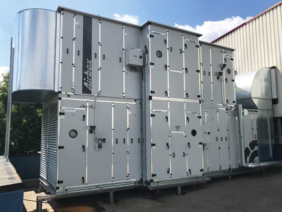
 An air handling unit, commonly called an AHU, is the composition of elements mounted in large, accessible box-shaped units called modules, which house the appropriate ventilation requirements for purifying, air-conditioning or renewing the indoor air in a building or premises.

They are usually installed on the roof of buildings and, through ducts, the air is circulated to reach each of the rooms in the building in question.


Air handling installation in the roof of a Hotel


Main functions of an AHU

In addition to managing the proper ventilation of the interior with outside air, the AHU performs other functions:

  • Filtration and control of the quality of the air that will reach the interior, thanks to the air purification filters, and depending on the retention of these filters, the air will be clean.
  • Control of the air temperature that regulates the air conditioning system in cold or hot, so that the thermal sensation in the interior is the desired one.
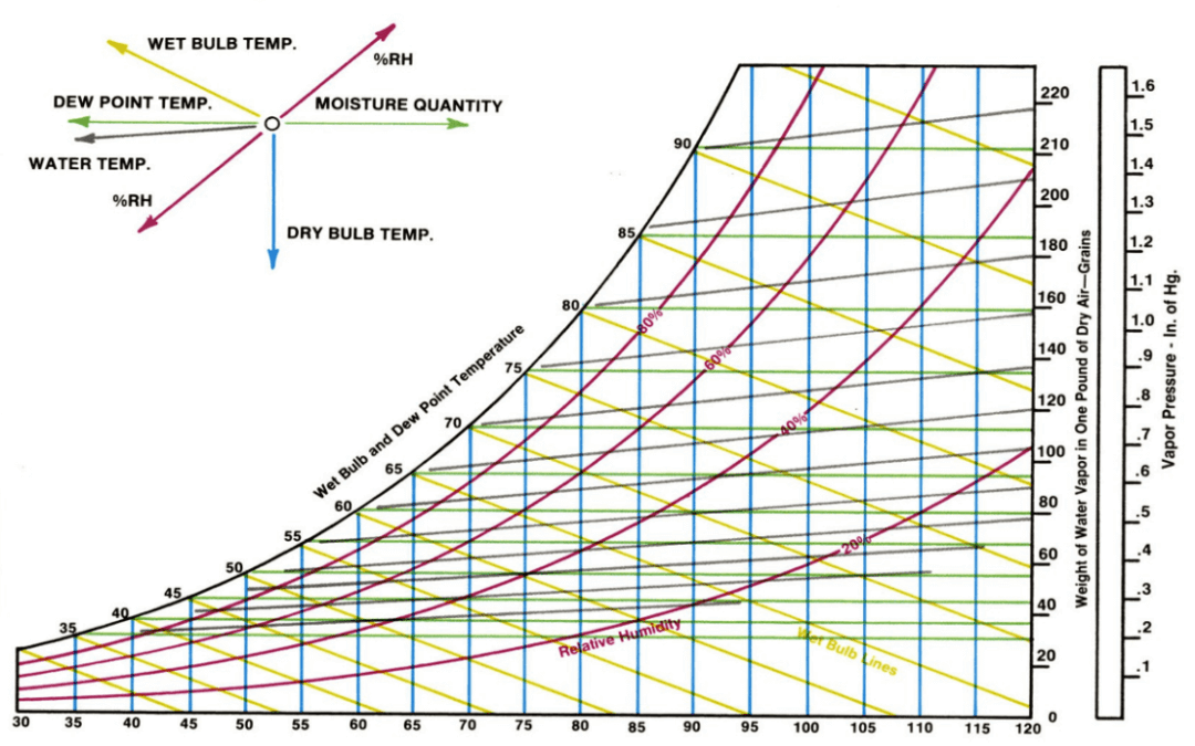
  • Relative humidity monitoring for greater indoor comfort.

For its part, the places for which the AHU is intended are those in which the flow of people is very large and accumulates many people at the same time and whose natural ventilation is limited: hotel dining rooms, function rooms, restaurants, convention halls... It is also a suitable option for those spaces with very high hygiene requirements: laboratories, clean rooms or operating theatres, among others. An AHU can also be used to ventilate places where air conditioning is provided by radiators or underfloor heating, for example.

What does an AHU consist of?


Sketch of the components of an Air Handling Installation

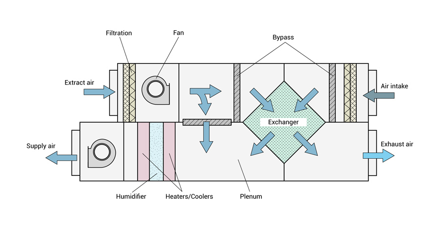
  • Air intake: air handling units collect air from outside, which is treated and distributed throughout the rooms; and/or indoor air that is "recycled".
  • Filter: depending on the air purity requirements, the filter applied will have a higher or lower particle, viruses, bacteria, odours, and other air pollutants retention.
  • Fan: this is an electromechanical system that powers the air to expel it from the AHU to the ducts that distribute the air throughout the rooms.
  • Heat exchangers: devices that transfer temperature between two fluids, in this case, coolant and air, separated by a solid barrier.
  • Cooling coil: the air passing through this module is cooled. In this process, water droplets can be generated, which are collected in a condensate tray thanks to the built-in droplet separator.
  • Silencer: coatings that considerably reduce the sound level of the installation.
  • Plenums: empty spaces in which the air flow is homogenised.

Energy efficiency of AHUs

The ultimate aim of an air handling unit is energy efficiency and this is mandatory since 2016 by the European Ecodesign Regulation 1235/2014.

By having heat recovery units, the AHU reduces the use of energy required in air conditioning, as in the exchanger, the indoor and outdoor air is mixed, so that when the air reaches the coil the temperature contrast is lower, therefore, the climatic contribution is also lower and energy consumption is also reduced.

Likewise, the variable regulation of the equipment means that the fans can work according to the flow rate needs, reducing their consumption.

Thursday 2 June 2022

Types of refrigerant used in refrigeration system

 Types of refrigerant used in refrigeration system

Refrigerants are divided into groups according to their chemical composition. Following the discovery that some of these chemical compounds may be harmful to the environment, they are being replaced with more environmentally friendly alternatives (see Figure 5.2). The process is not easy, and although there are alternatives to old refrigerants, the new ones are usually not flawless.
In the following section, different groups of refrigerants are discussed, some examples are given and their fields of application are described.

CFC = ChloroFluoroCarbons

Chlorofluorocarbons are refrigerants that contain chlorine. They have been banned since the beginning of the 90's because of their negative environmental impacts. Examples of CFCs are R11, R12 and R115. The conversion of equipment and systems using CFCs has not yet been completed. On the contrary, the illegal market for this type of refrigerants flourishes worldwide, and it is estimated that no more than 50% of CFC systems worldwide have been upgraded.

HCFC = HydroChloroFluoroCarbons

The slow phase-out of CFCs shows it is a costly process. However, and more importantly, it also shows the problems and indecisiveness surrounding the availability of HCFCs, which were officially indicated as temporary (until 2030) substitutes for CFCs. The hasty actions of the European Union that culminated in the ban of HCFCs, immediately for refrigeration and soon (2004 at the latest) for air conditioning, has upset the industry's programs and plans.

The HCFCs contain less chlorine than CFCs, which means a lower ODP (see section 5.3). Examples of hydrochlorofluorocarbons include R22, R123 and R124 (see Figure 5.3).


HFC = HydroFluoroCarbons

The hydrofluorocarbons are refrigerants that contain no chlorine and are not harmful to the ozone layer (ODP = 0, see section 5.3). However, their impact on global warming is very large compared with traditional refrigerants. The most common HFC refrigerants available since the ban on HCFCs are presented in Table 5.1 (see also Figure 5.4):


Table 5.1 The most common refrigerants among halogenated hydrocarbons.

Some comments on the refrigerants presented in the table are given below:

  • R32 and R125 are seldom used as single refrigerants, but only in mixtures with particularly favorable thermodynamic properties.
  • R245c and R245fa are used almost exclusively in the United States and in a rather experimental way.
  • R404A has been developed as an alternative to R502 for refrigerators and freezers.
  • R134a was the first HFC introduced in refrigeration and air conditioning with great success, because it requires almost no changes in the equipment designed for R22. However, it offers a very limited efficiency, about 40% lower than that obtained with R22. Consequently, the manufacturer has two choices: either to accept a substantial reduction in the thermal capacity in a given system, or to increase its dimensions (and cost) to achieve the same capacity. For this reason, R134a is used mainly in large systems (over 250 kW) that can afford the higher costs.
  • R407C is, like R134a, thermodynamically similar to R22 and works as a "drop in" refrigerant. However, unlike R134a, which is a pure compound, R407C has a glide of 7 K, making it barely usable in small residential (household) equipment. There are two reasons to justify such a limitation: residential equipment is more subject than other equipment to sudden accidental losses, and it is usually serviced on site. In the event of a sudden leakage, a 7K glide may result in changes in the proportions of the mixture, because the relative losses of its most volatile components will be disproportionately high. If a standard refill is used, there is no guarantee that the new refrigerant mixture has the same proportions as it had before the leakage. Due to its high glide, this refrigerant is used only in medium-capacity systems (50-250 kW), which are usually serviced by skilled personnel.
  • R410A has very attractive thermodynamic properties, higher energy efficiency than R22, no glide and hence no problem with the mixture remaining after charge loss and refill. However, it has an operating pressure almost double that of R22, and therefore requires a redesign of the whole system with larger compressors, expansion valves, etc.
  • R507A is used successfully in industrial and commercial refrigeration.
  • R508B is less frequently used in low temperature cycles. R507A and R508B have favorable thermodynamic properties and no problems with temperature glides, because they are azeotropic mixtures.

FC = FluoroCarbons

Fluorocarbons (Figure 5.5) contain no chlorine and are not harmful to the ozone layer. However, they are extremely stable, and they have a high GWP (cf. section 5.3). R218 is an example of a fluorocarbon, and FCs are also present in the mixtures R403 and R408.


HC = HydroCarbons

Hydrocarbons are a very limited solution to the environmental problems associated with refrigerants. They are harmless to the ozone layer (ODP = 0) and have hardly any direct green house effect (GWP<5), but they are highly flammable. The use of HCs as refrigerants is confined to Europe, because many other countries elsewhere have banned the use of flammable gas in the presence of the public. According to the standards ISO 55149 and EN 378.2000, this should apply also in Europe. However, the standard IEC 355.2.20 allows the use of HCs in household refrigerators with refrigerant charges up to 150 g.

This standard has opened the way for some European refrigerator manufacturers to produce household refrigerators with flammable isobutene, R600a.

These have been accepted enthusiastically by environmentalists, and have achieved great success in the market.

NH3 = Ammonia

Ammonia, R717, is an attractive refrigerant alternative. It has been used in refrigeration systems since 1840 and in vapor compression since 1860. In terms of its properties, it should be considered a high-class refrigerant. Furthermore, its ODP and GWP are 0. However, although it is a selfalerting gas, i.e. leaks can easily be detected by the smell, ammonia is very hazardous even at low concentrations because the smell often causes panic. This is the main reason why ammonia was withdrawn from applications for use by unskilled people and retained only for industrial applications.

It is also quite common in commercial refrigeration, although safety regulations require that it be used with a secondary distribution loop. Obviously, this secondary loop reduces the efficiency.

CO2 = Carbon Dioxide

R744, carbon dioxide, has several attractive characteristics: non-flammable, does not cause ozone depletion, very low toxicity index (safety A1), available in large quantities, and low cost. However, it also has a low efficiency and a high operating pressure (approximately 10 times higher than R134a). For the two latter reasons, efforts are needed to improve its refrigeration cycle and related technology, particularly heat exchangers and expansion devices. A major forthcoming CO2 application seems to be air conditioning in the automotive industry. Heat pumps could also benefit from CO2 due to the higher temperature that can be obtained even at very low ambient temperatures.

Summary Table


PSYCHROMETRIC CHART USE


DOWNLOAD A PSYCHROMETRIC CHART FROM PARAMETER GENERATION & CONTROL

Parameter Generation and Control now offers website visitors a free, downloadable PDF of the psychrometric chart. If carrying out heat load or cooling load calculations with a humidity control room or humidity chamber, turn to the psychrometric chart as an initial resource to understand the relationship between the different variables in air. For more information on our chamber and control room product and service offerings, contact us to request a quote today.

WHAT IS A PSYCHROMETRIC CHART?

A psychrometric chart represents the psychrometric properties of air. With this chart, engineers can better assess psychrometric processes and find practical solutions. While this chart looks complicated and even intimidating, it’s actually quite helpful and simple to understand once you grasp the basic properties of air. If you know two parameters of air where the lines will cross each other, the psychrometric chart can do the rest of the work for you.


THE BENEFITS OF USING A PSYCHROMETRIC CHART CORRECTLY

A psychrometric chart prevents engineers from spending time on tedious mathematical formulas. While there are online calculators and applications to help make calculations, using the chart correctly provides engineers with a more accurate reading as long as you know two parameters of air. Knowing how to read a psychrometric chart is a wise skill for engineers to have in the event that technology fails or isn’t available.


WHAT ARE THE PARTS OF A PSYCHROMETRIC CHART?

A psychrometric chart consists of eight standard parts, including:

  • Temperatures
    • Dry Bulb – This is the temperature reading found on a typical thermometer. You can find a psychrometric chart that offers these temperature ranges:
      • Low temperatures that range from -20 degrees FDB to 50 degrees FDB
      • Normal temperatures that range from 20 degrees FDB to 100 degrees FDB
      • High temperatures that range from 60 degrees FDB to 250 degrees FDB
    • Wet Bulb – This is a typical thermometer’s standard reading if the sensing bulb is covered with a wet wick or sock and exposed to air flow.
    • Dew Point – At this temperature, moisture starts condensing from the air.
  • Specific Volume & Density – Specific volume is measured in cubic feet per pound. This refers to the amount of space air occupies per pound of weight.
  • Enthalpy – This is the measurement of heat energy. Enthalpy is measured by Btu (British thermal unit) per pound of dry air. 
  • Sensible Heat Ratio – This is the total sensible heat flow divided by the total heat flow.
  • Sensible Heat Flow – 60(specific heat of air in Btu/lb ºF (0.24 at 72ºF))(density of air in lb/ft³)(air flow in ft³/min)(| supply air temperature – conditioned room temperature |) 
  • Latent Heat Flow – 60(latent heat of vaporization of water in Btu/lb (970 at sea level))(density of air in lb/ft³)(air flow in ft³/min)(humidity ratio difference in lb water/lb dry air)
  • Moisture Content – Also known as the humidity ratio, this is the total weight of water vapor per pound of dry air.
  • Relative Humidity – This refers to the percentage of water vapor per pound of dry air in relation to how much the air can hold at its current temperature.
  • Vapor Pressure – Vapor pressure is measured in inches of mercury and represents the pressure exerted by water vapor in air.
  • Standard Air Dot – This dot marks the measurement for standard air. Standard air is typically 70 degrees Fahrenheit with a relative humidity of 54% and 60 gr/lb of specific humidity.


HOW TO READ A PSYCHROMETRIC CHART

A psychrometric chart can easily be read by following these steps:

Step 1: Locate the dry bulb temperature. This will be measured in degrees Fahrenheit or Celsius and will be along the bottom axis. Also identify the vertical line for each temperature.

Step 2: Locate the humidity ratio, sometimes labeled as a mixing ratio. This will be along the right vertical axis. Humidity ratio units are grains of moisture per pound of dry air or grams of moisture per kilogram of dry air.

Step 3: Located the left-most curved line. This refers to the saturation curve where relative humidity is 100%. 

Step 4: Locate the interior curved lines, which represent percentage levels of relativity humidity.

Step 5: Locate the dew point. This is a vertical line on the right side of the chart. These lines traverse the chart as horizontal lines.

Step 6: On the other side of the dew point’s vertical line is the vapor pressure scale. Vapor pressure lines also traverse the chart as horizontal lines.

Step 7: On all outer sides of the chart, you’ll see scales representing enthalpy. With a ruler, you can match the scales across the chart. 

Step 8: Find the second set of diagonal lines which identify wet bulb temperature. Though these lines are close to the enthalpy lines, they’re not actually parallel. 

When using Airtable’s PDF psychrometric chart, there are some formational aspects to be aware of. First, the properties of air indicated in the chart are calculated at standard atmospheric pressure. For other pressures, relevant corrections have to be applied.

Also note that the relative humidity lines are the curves extending from the lower left to the upper right portion of the chart. The relative humidity curves indicate different values of humidity measured in percentage. The value of relative humidity reduces from left to right.

What is AHU?

  An air handling unit, commonly called an   AHU , is the composition of elements mounted in large, accessible box-shaped units called modul...